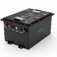
Thinking about upgrading from lead-acid to lithium-ion forklift batteries? Learn how lithium forklift batteries are assembled to help inform your decision.

Cleaning the Computer Case
Before assembling the battery pack, the interior of the battery enclosure must be thoroughly cleaned and inspected to ensure that the installation environment meets the requirements.
During manufacturing processes such as welding, cutting, and grinding, welding slag, weld spatter, metal burrs, metal shavings, or other sharp foreign objects may remain inside the enclosure. If these contaminants are not promptly removed, they may come into contact with the battery casing or PVC insulation film during subsequent battery module installation, causing the insulation film to be scratched or damaged. In severe cases, this could lead to battery short circuits or insulation failure.
During the cleaning process, first inspect the inner walls, welded areas, and corners of the enclosure, focusing particularly on removing protruding weld spatter and sharp burrs caused by welding. For obvious metal protrusions, use grinding tools to smooth them down, ensuring the interior surface of the enclosure is flat and preventing direct contact between the battery modules and sharp edges.
After removing burrs, thoroughly clean the interior of the enclosure with a vacuum cleaner to remove any remaining metal debris, dust, and other foreign matter.
Particular attention should be paid to the bottom of the enclosure, corners, and areas near weld seams, as these are locations where foreign matter tends to accumulate; therefore, these areas require thorough cleaning. Once cleaning is complete, inspect the interior again for any overlooked sharp objects or particles to ensure the enclosure is clean and free of foreign matter.
This process effectively reduces the risk of enclosure wear and damage to the insulation layer during battery installation, providing a safe and reliable foundation for the subsequent assembly, securing, and full-pack testing of the battery modules.

Module Placement
In accordance with the requirements of the design drawings, place the battery modules into the chassis one by one in the specified positions, ensuring that the installation orientation, sequence, and position of each module match the illustrations. During installation, first verify the chassis's positioning structure and mounting holes, then place the modules one by one according to the predetermined layout to avoid misalignment or incorrect installation.
Once placement is complete, secure the modules to the designated positions in the enclosure using screws to ensure a firm connection and prevent the modules from loosening due to vibration during vehicle operation. At the same time, control the tightening force of the screws to prevent damage to the module casings caused by over-tightening.
After installing all modules, recheck that the positive and negative terminals of the battery modules match the markings on the design drawings to ensure correct polarity and prevent short circuits or connection errors during subsequent wiring. Additionally, inspect the spacing, positioning, and securement of the modules to ensure the overall layout meets design requirements, preparing for subsequent wiring harness connections and battery pack testing.

Module Installation and Connection
Select the appropriate connector tabs according to the BOM requirements, ensuring that their dimensions, thickness, and current-carrying capacity meet the battery pack's design specifications. Before installation, verify the connection sequence and polarity direction for each module based on the "Layout Diagram" to prevent battery pack malfunctions caused by incorrect connector tab specifications or installation orientation.
Connect the modules according to the red series connection routes marked on the drawings, starting from the common negative terminal and proceeding step by step in the design direction toward the common positive terminal. During this process, strictly verify the positive and negative terminal positions of each module to ensure that the connectors are accurately attached to the corresponding terminals and to prevent reverse polarity.
Before proceeding with the series connection, inspect the position, polarity, and voltage status of all modules. Proceed with the connection only after confirming everything is correct to prevent short circuits or battery damage caused by incorrect connections.
After installing the connectors, secure them with screws and use a torque wrench to tighten them to the specified torque to ensure reliable contact between the connectors and the terminals, while avoiding terminal damage caused by excessive torque. Do not fully tighten the screws at the locations corresponding to the voltage sensing wires; wait until the voltage sensing wires have been installed before securing them.
After all connectors have been secured, apply anti-loosening adhesive to the screw threads to prevent the screws from loosening due to vibration while the vehicle is in operation.

Connect the power line
Based on the battery pack's electrical layout diagram, connect the power cables to the designated positive and negative output terminals. Before installation, verify that the power cables meet the battery pack's design requirements-including wire gauge, length, terminal specifications, and connection orientation-to ensure they can handle the battery pack's operating current demands.
When making connections, connect the positive power cable to the battery's positive busbar and the negative power cable to the battery's negative busbar as specified in the drawings, and verify that the wiring harness routing matches the layout diagram. During installation, avoid excessive bending or crushing of the cables, and ensure they do not come into contact with sharp edges of the enclosure. Ensure the wiring harness is neatly arranged to prevent wear during subsequent use.
After installing the power cable terminals, inspect the fit between the terminals and the battery posts to ensure good contact at the connection surfaces. Tighten the screws to the specified torque to guarantee the reliability of the power connection and prevent issues such as overheating or abnormal current transmission caused by poor contact.
Connection Fuse
Install and connect the fuse to the designated location according to the battery pack design drawings. Fuses are typically connected in series with the power circuit and can cut off the circuit in the event of an overcurrent or short circuit, thereby protecting the battery pack and external equipment.
During installation, ensure that the fuse's orientation, connection points, and rated specifications comply with the BOM requirements.
Connect the fuse's input and output terminals to the corresponding circuits, respectively. After completion, verify that the fuse is securely fastened and that the terminal connections are tight to prevent increased contact resistance caused by loose connections.
Finally, double-check that the connections between the power lines, the fuse, and the battery's positive and negative terminals match the design drawings.

Install the BMS
Determine the installation location of the Battery Management System according to the "Installation Diagram." Position the BMS correctly in the designated area inside the chassis, and ensure that the installation orientation meets design requirements. Before installation, inspect the BMS for any damage and verify that the interfaces, mounting holes, and wiring harness connection points match the battery pack's design.
During installation, use M4 anti-slip nuts and washers to secure the BMS to the mounting bracket or designated location inside the chassis, ensuring a secure fit to prevent the BMS from loosening due to vibration during vehicle operation. At the same time, pay attention to the installation sequence and orientation of the mounting screws to ensure that components such as washers and anti-slip nuts are installed correctly.
After securing the BMS, check the installation clearance between the BMS and the chassis to prevent the BMS housing from colliding with or interfering with other metal components, and confirm that the BMS's position will not interfere with the subsequent connection and routing of power, sampling, and communication harnesses.

Installing the wiring harness
Install in accordance with the BMS interface specifications and the wiring harness labels. First, insert the data acquisition harness into the corresponding data acquisition interface on the BMS. Before installation, verify that the wiring harness label matches the BMS interface number to prevent incorrect connections that could lead to abnormal voltage data readings. When inserting, ensure that the connector is fully seated and that the latches are securely engaged to guarantee stable signal transmission.
Next, install the control harness. Insert the control wire terminals into the corresponding control interfaces on the BMS, matching them according to the interface markings. Verify that the plug type and orientation are correct to prevent control malfunctions caused by improper or incorrect connection.
After completing the connections for the data acquisition and control wires, connect the PE wire to the BMS's fixing terminal. During installation, ensure that the PE wire terminal makes good contact with the fixing terminal and secure it reliably with screws to ensure the stability of the protective earth connection.
Finally, organise the wiring harness according to the routing requirements inside the enclosure, lay the harness along the planned path, and secure the control wiring harness to the side panel of the electronic control unit using cable ties. When securing the harness, ensure that it is not loose, pinched or pulled, whilst also avoiding direct contact between the harness and any metal edges.

Fitting the case cover
Install the enclosure cover in accordance with the requirements of the assembly drawing. Prior to installation, ensure that all modules, power cables, the battery management system, wiring harnesses and connectors inside the enclosure have been fully installed, and check the interior for any omitted tools or foreign objects to ensure that no damage is caused to internal components during the installation of the enclosure cover.
During installation, position the enclosure cover above the enclosure in the direction specified by the design, ensuring that the positioning holes on the cover align with the mounting holes on the enclosure. Throughout the installation process, pay close attention to how the cover fits against the edges of the enclosure to ensure it is installed flat, avoiding any misalignment, warping or interference.
Once the enclosure cover is in position, secure it using the designated screws. In accordance with the design specifications, tighten all fixing points in sequence to ensure the enclosure cover is securely attached to the enclosure. During tightening, apply the appropriate torque to prevent the screws from becoming loose or the cover from deforming due to over-tightening.

Installing a PDU
In accordance with the requirements of the assembly drawing, install the PDU (Power Distribution Unit) in the designated position within the chassis. Prior to installation, verify that the PDU model, installation orientation and interface locations correspond to the design drawing, and check that the mounting holes align correctly to ensure the accuracy of the installation position.
During installation, place the PDU onto the corresponding bracket inside the chassis, ensuring that the mounting holes are aligned with the installation holes, and then secure it with screws. Whilst securing the unit, ensure that the PDU is firmly fixed to prevent it from becoming loose due to vibration whilst the vehicle is in motion. At the same time, take care to avoid any interference between the PDU housing and other components.
Once the PDU has been secured, connect the positive and negative power cables from the battery to the corresponding input terminals on the PDU in accordance with the electrical connection requirements, and confirm that the cables are connected in the correct direction. During connection, check that the terminals are fully seated and tighten the screws to the specified torque to ensure the reliability of the power connection and prevent overheating caused by poor contact.

Manufacturing and assembly of REMA connectors
In accordance with the assembly requirements for REMA connectors, the auxiliary contact wiring harness must be assembled first. Once the auxiliary contacts have been soldered, slip the wire-marking tubes over the outside of the harness, ensuring that the wire markings are clear and correctly positioned to facilitate subsequent wiring and maintenance.
Next, install the main contact cables. In accordance with the polarity requirements, use a red cable for the positive terminal and a black cable for the negative terminal, ensuring that the cable colours correspond to the polarity to avoid wiring errors during installation.
Once the cables are ready, insert the contact pins into the corresponding sockets of the REMA connector as shown in the diagram. During installation, ensure that the position of each pin matches its defined function-including the positive terminal, negative terminal, auxiliary contacts and communication interface-to prevent incorrect insertion.
Once the pins have been inserted, check that they have been pushed fully into the connector to ensure they are seated to the end and locked in place. After confirming that all pins are secure, fit the connector retaining plate into position to secure the internal contacts and prevent the pins from becoming loose or falling out during use.
Next, fit the anti-misinsertion insert (anti-misinsertion mechanism) from the front of the connector. During installation, pay attention to the correspondence of voltage positions to ensure that the position of the anti-misinsertion insert matches the battery voltage specification, thereby preventing incorrect connections between systems with different voltages.
Finally, use the screws supplied with the REMA to install the cable clamp to secure the main power cable. When tightening the screws, ensure that the clamp effectively secures the cable whilst avoiding damage to the cable sheath.

Creating force lines
In accordance with the requirements of the 'Power Cable Diagram', select the appropriate cable diameter and terminal type to ensure that the current-carrying capacity of the power cables, the terminal dimensions and the connection method all comply with the battery pack's design requirements. Before commencing fabrication, it is essential to confirm the cable type, length and terminal specifications to avoid any issues with subsequent installation and use arising from specification mismatches.
When cutting the cable, ensure that the cut is clean and perpendicular to the cable's axis to prevent inconsistent copper core lengths or compromised crimping results caused by an angled cut. After cutting, strip the cable according to the terminal requirements, ensuring the stripped length is sufficient for the copper core to be fully inserted into the terminal.
After stripping, insert the exposed copper core into the base of the terminal, ensuring it is fully inserted, whilst checking the gap between the insulation and the rear of the terminal to ensure it does not exceed 0.5 millimetres. Avoid leaving the copper core exposed for too long or allowing the insulation to enter the crimping area, as this may compromise the reliability of the connection.
When crimping the terminal, select the appropriate crimping die according to the cable specifications and position the terminal correctly, ensuring that the crimping point is centred within the terminal. During the crimping process, apply pressure from different directions as required, crimping at least three times in each direction to ensure the terminal is fully bonded to the copper core, thereby guaranteeing its mechanical strength and electrical conductivity.
Once crimping is complete, a tensile test must be carried out in accordance with the requirements for the corresponding wire gauge to ensure that the connection strength between the terminal and the cable meets the relevant standards. After the test has been passed, the crimped area should be protected with heat-shrink tubing. The length of the heat-shrink tubing should cover the crimped area of the terminal and be at least twice the length of the crimped section to ensure that the connection is adequately insulated and mechanically protected.

Install the Charge/Discharge Connector
Install the charging and discharging connector at the designated location on the battery pack according to the assembly drawing requirements. Before installation, verify that the connector model, interface orientation, and installation location match the design drawing, and inspect the connector's appearance to ensure it is free of damage or deformation.
During installation, secure the charging and discharging connector to the corresponding mounting location on the chassis, ensuring that the connector's mounting holes align with the chassis's mounting holes, and then fasten it with screws. During installation, ensure the connector is installed flat and securely fastened to prevent vibration during vehicle operation caused by a loose connector.
After securing the connector, connect the positive power wire to the connector's positive terminal and the negative power wire to the connector's negative terminal, in accordance with the electrical connection requirements. Verify that the cable polarity matches the interface markings to avoid reverse connections. When connecting, ensure that the terminals make full contact with the connection points and tighten the mounting screws to the specified torque to ensure stable current transmission.
After connecting the power wires, organize the connector harness, route the cables into place according to the design diagram, and secure the harness with fasteners to prevent it from becoming loose, being pulled, or rubbing against the edges of the chassis.

Power-On Test
Using a multimeter, touch the red probe to pin 1 at the X terminal on the control cable and the black probe to pin 15. Pull the emergency stop switch, then press and hold the start switch. If the multimeter displays "+12V," the connection is correct. Next, release the switch, plug in the X terminal, and press and hold the start switch for 3 seconds before releasing it. If the battery voltage is present during discharge, this indicates that the system is functioning normally. Finally, temporarily secure the top cover of the chassis and wait for the full system test.
Still have questions about installing lithium-ion forklift batteries?
CoPow is a professional lithium forklift battery manufacturer. Over the past five years, we have successfully installed new lithium-ion forklift batteries for many users and warehouse managers who previously used lead-acid forklift batteries.
Whether it's battery specifications, relays, DC converters, fuses, and other accessories, or battery management systems, various communication protocols, battery sizes, and module assembly methods, we have accumulated extensive experience.
If you also need to replace your forklift batteries or upgrade from old lead-acid batteries to lithium-ion batteries, feel free to contact our battery engineers at any time to discuss the feasibility of solutions and receive professional advice.